
Turn-Mill Machining | | 6-8 min read
How to Maintain Feature Position Accuracy in Turn-Milled Cylindrical Parts
A cylindrical component may appear straightforward until it also requires cross holes, counterbores, flats, slots, threaded side holes or other milled features.
Feature position accuracy depends on datum selection, workholding, angular positioning, machining sequence, material behavior, tool condition and inspection strategy.
Published by the DXSCNC Engineering Team.
Introduction
In these parts, the difficulty is often not achieving the size of one individual feature. A hole diameter may be within tolerance, a thread may pass its gauge and the outside diameter may also be correct, yet the part can still create assembly problems if those features are not positioned correctly relative to the cylindrical axis and to one another.
This technical note explains the main factors that affect positional relationships in turn-milled cylindrical components and how manufacturers can reduce avoidable variation. It also connects the guidance to a real DXSCNC black POM production example without presenting confidential or unsupported project data.
On This Page
Why Individual Dimensions Are Not Enough
A drawing may specify the diameter of a cross hole, the depth of a counterbore and the thread size of a side hole. These dimensions describe the individual features, but they do not fully describe whether the features will function together.
For example, a cylindrical component may require:
- A cross hole aligned with a longitudinal milled feature
- Two side holes positioned at a defined angular relationship
- A counterbore concentric with its pilot hole
- A threaded side hole located from an end face
- End threads aligned with the principal cylindrical axis
- A slot centered relative to the outside diameter
Each individual feature may meet its own size tolerance while the overall part still fails to assemble correctly because of angular, axial or radial displacement. Manufacturers must therefore treat the outside diameter, end face and cylindrical centerline as part of a connected datum system rather than as unrelated dimensions.
Common Sources of Feature Position Error
Several small variations can combine to create a larger positional error.
1. Inconsistent machining references
If turned features and milled features are established from different or poorly related references, their accumulated relationship may become difficult to control. A stable cylindrical surface, a controlled end face and the primary axis of the part normally provide useful references for locating side features. The exact datum strategy must follow the engineering drawing.
2. Repeated workpiece alignment
Every additional removal, rotation or reclamping operation can introduce another opportunity for alignment variation. This does not mean that every complex cylindrical component must be completed in one setup. Some geometries require multiple operations. The important point is that every operation must return to a controlled and repeatable reference.
3. Angular positioning variation
Cross holes and milled features depend on the rotational position of the component. A small angular variation becomes a measurable linear position error at the outer surface. The effect becomes more important when several side features must maintain a precise relationship around the circumference.
4. Clamping deformation
Thin-walled, long or plastic components can deform when clamping pressure is excessive or uneven. A diameter measured while the part is clamped may change after release. Deformation can also influence the true position of holes or milled surfaces relative to the free-state cylindrical axis.
5. Cutting forces and heat
Cutting pressure and heat can influence dimensional stability, particularly in engineering plastics such as POM. Tool sharpness, cutting engagement, chip evacuation and machining sequence should be selected to avoid unnecessary heat accumulation and material deflection.
6. Burrs and incomplete edge control
Burrs can interfere with measurement, thread engagement and assembly. A small burr around a cross hole can also make a feature appear dimensionally or positionally incorrect during inspection. Deburring must be controlled without rounding functional edges or changing feature size.
Establishing a Reliable Cylindrical Reference
A good positional-control strategy begins with clear references. For many cylindrical components, the relevant references include:
- The principal cylindrical axis
- A controlled outside or inside diameter
- One functional end face
- A secondary flat, slot or orientation feature
The cylindrical axis controls radial and angular relationships. The end face establishes axial location. A secondary orientation feature may be required when several holes or milled features must be clocked relative to one another.
The manufacturing process should follow the drawing datum structure wherever one is defined. When the drawing does not clearly communicate functional datum relationships, the manufacturer should request clarification before production rather than making assumptions.
A dimensional tolerance alone does not always communicate assembly function. Position, concentricity, runout, perpendicularity or profile requirements may also be relevant, depending on the part. Review the relationship between CNC turning references and later side-feature operations before production.
Controlling Cross Holes, Counterbores and Threaded Side Features
Cross holes appear simple, but their location can depend on several variables at the same time:
- Axial distance from the end face
- Radial relationship to the part axis
- Angular orientation around the circumference
- Relationship to a second hole, slot or flat
- Hole straightness and breakthrough condition
Counterbores introduce an additional relationship between the larger recess and the pilot hole. The two features must remain aligned, and the counterbore depth must also be controlled.
Threaded side holes require attention to both position and thread quality. A correctly formed thread located in the wrong position is still a nonconforming functional feature. Where possible, the machining strategy should use common references for connected features. This reduces the number of independent alignment steps and makes the relationship between turning and milling operations easier to control.
How Turn-Mill Machining Can Help
Turn-mill machining combines rotational cutting with milling, drilling and other non-axisymmetric operations within a coordinated machining process.
For suitable components, this approach can reduce repeated transfers between separate machines and can maintain a more direct relationship between the turned cylindrical references and the milled side features. Potential advantages include:
- Fewer independent alignment operations
- Controlled angular positioning of side features
- Better relationship between the cylindrical axis and milled geometry
- Reduced handling between turning and milling processes
- More consistent processing of repeated production parts
Turn-mill machining is not automatically the best process for every component. Part length, diameter, wall thickness, material, tooling access, feature orientation, tolerance requirements and batch size must all be considered. Some parts may still require secondary machining or dedicated fixtures.
The correct objective is not to force every feature into one setup. It is to use the most stable and repeatable process for the drawing requirements.
Special Considerations for Long Cylindrical Parts
As the length-to-diameter ratio increases, a cylindrical component becomes more sensitive to workholding and cutting forces. Possible risks include:
- Deflection during machining
- Diameter variation along the length
- Vibration or chatter
- Surface marking from clamping
- Misalignment after reclamping
- Distortion after the part is released
The process may require balanced clamping pressure, suitable support, controlled roughing and finishing sequences, and measurements taken in the correct free-state condition. The support method depends on the part geometry and must not be assumed from appearance alone.
Special Considerations When Machining POM
POM is widely used for machined engineering components because it offers useful dimensional, friction and machinability characteristics. However, it behaves differently from metal during machining. Buyers can use the POM CNC machining material review path when preparing a drawing package.
Clamping pressure
Excessive clamping can temporarily distort the component. After release, the part may recover and produce a different measured dimension.
Cutting heat
Engineering plastics have different thermal behavior from metals. Excessive heat can contribute to dimensional variation and poor surface condition.
Tool sharpness
Sharp cutting edges help reduce cutting forces, heat and burr formation.
Chip control
Long or poorly evacuated chips can interfere with the cutting area and affect surface quality.
Burr control
Holes, threads and milled edges should be inspected carefully for residual burrs without removing functional material.
These considerations become more important when a POM component combines a relatively long cylindrical body with several position-sensitive side features.
Machining Sequence and Production Consistency
A stable machining sequence should preserve the references needed by later operations. A typical planning logic may include:
- Establish the principal cylindrical and axial references.
- Machine the required turned features.
- Produce side features using controlled angular and axial positioning.
- Complete thread and counterbore features.
- Remove burrs without altering functional geometry.
- Inspect the connected feature relationships.
- Monitor consistency throughout the production batch.
This sequence is only a general planning framework. The actual order depends on part geometry, material, tolerances and machine access.
For production quantities, manufacturers should not rely only on a final inspection of randomly selected parts. First-piece confirmation, process monitoring and appropriate sampling help identify dimensional drift before it affects a large quantity.
Inspection Methods for Position-Sensitive Cylindrical Parts
Inspection must evaluate both individual feature dimensions and their relationships. Depending on the drawing requirements, suitable methods may include:
- Micrometers for outside diameters
- Bore gauges or suitable internal measuring tools
- Thread plug gauges
- Height gauges and surface plates
- Dial indicators for runout-related checks
- Optical measuring systems
- Coordinate measuring machines
- Dedicated checking fixtures
- Surface roughness instruments
The selected method must be capable of resolving the specified tolerance. A standard caliper may be suitable for a noncritical overall dimension but may not be adequate for evaluating a tight positional relationship between multiple features.
Inspection records should identify the drawing characteristic being checked rather than simply listing instrument readings without reference to function. See DXSCNC's precision inspection approach for drawing-based critical-feature planning.
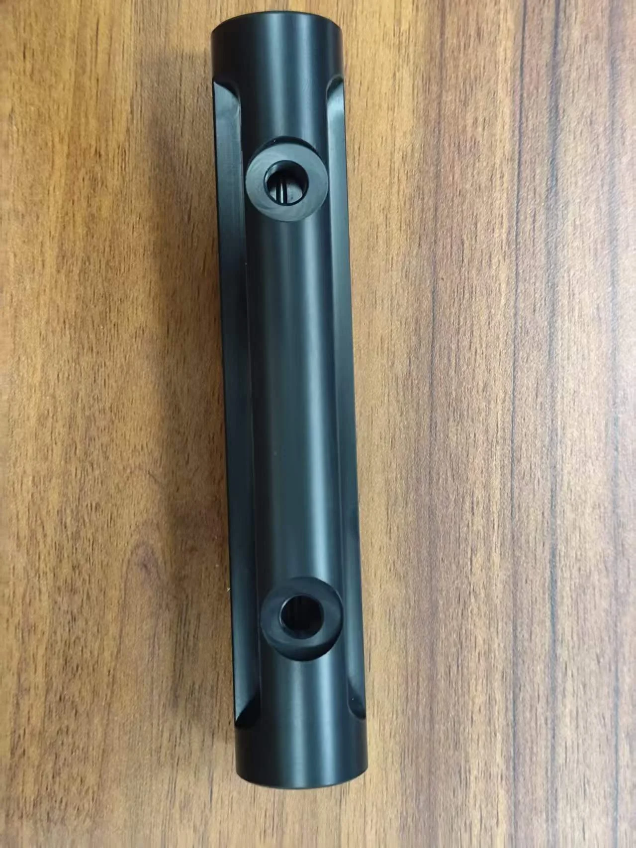
Real Manufacturing Example: Black POM Cylindrical Component
DXSCNC manufactured a production batch of 500 long cylindrical mounting components from black POM. The documented project specifications included:
- Quantity: 500 pieces
- Approximate size: 35 mm diameter x 160 mm length
- Outside diameter tolerance: +/-0.03 mm
- Internal M15 threads at both ends
- Surface roughness: Ra 1.6 um
- Multiple cross holes, counterbores, threaded holes and longitudinal milled features
The key manufacturing consideration was maintaining the positional relationship between the different side features and the principal cylindrical geometry throughout the batch. This example illustrates why a part that appears to be primarily cylindrical may require much more than basic turning.
View the complete Black POM Long Cylindrical Mounting Component case study for real DXSCNC photographs and the approved public project facts. Customer identity, application, drawing number, inspection records and confidential dimensions remain undisclosed.
Drawing Information Manufacturers Need
For an accurate manufacturing review, the drawing should clearly communicate:
- Material grade
- Overall dimensions
- Functional datum references
- Critical diameter tolerances
- Hole and counterbore dimensions
- Angular relationships
- Thread type, size, pitch and class
- Position or runout requirements
- Surface roughness
- Edge and burr requirements
- Inspection or reporting requirements
- Required quantity
A 3D model is valuable for geometry, but it should not replace a controlled 2D drawing when tolerances, threads, surface condition and inspection criteria are important. Send both files where possible when you request a CNC machining quote.
Frequently Asked Questions
What causes cross-hole position errors in cylindrical parts?
Common causes include inconsistent datum references, angular positioning variation, repeated alignment, part deformation, tool deflection and measurement uncertainty. The actual cause must be evaluated from the specific geometry and process.
Is turn-mill machining better for parts with multiple side features?
It can be advantageous because turning and side-feature machining can be coordinated around common references. However, suitability depends on part size, geometry, material, tolerance, tooling access and production quantity.
How are positional relationships inspected in production?
Depending on the tolerance and geometry, manufacturers may use height gauges, optical systems, dial indicators, coordinate measuring machines or dedicated fixtures. The inspection method must be appropriate for the specified tolerance.
Can long POM cylindrical components be machined accurately?
Yes, but workholding pressure, cutting heat, tool condition, support, machining sequence and free-state inspection must be controlled according to the component requirements.
What files should be provided for quotation?
Provide a 2D drawing and a STEP file where possible, along with the material grade, quantity, critical tolerances, thread details, surface requirements and inspection expectations.
Need a Turn-Milled Cylindrical Component?
DXSCNC manufactures precision turned and turn-milled components with cross holes, counterbores, internal and external threads, milled flats, slots and other position-sensitive features.
Send us your 2D drawing, STEP file, material, quantity and critical positional requirements for a manufacturing review and quotation.
Engineering review before quotation
DXSCNC will review datum relationships, workholding, feature access, burr risk and inspection feasibility against the submitted drawing.