Centerline to milled-feature relationship
Longitudinal milled features and side holes must be positioned relative to the turned cylindrical centerline and end references defined by the drawing.

Real Manufacturing Case
A real DXSCNC production example for a 500-piece black POM cylindrical component combining turned references, internal M15 end threads and position-related milled side features.
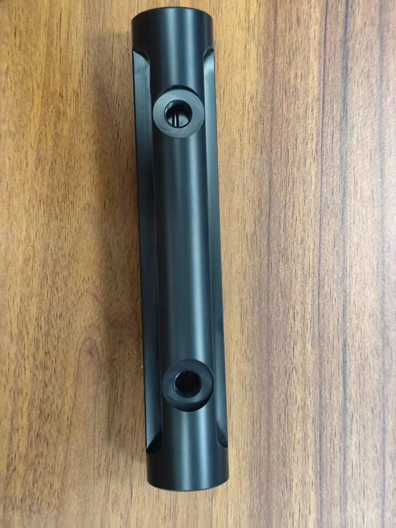
This page uses DXSCNC-owned product photos and approved public project facts. Customer identity, drawing number, application, order value, exact thread pitch, inspection records and confidential dimensions are not published or inferred.
| Page type | Real Manufacturing Case Study |
|---|---|
| Component | Long cylindrical mounting component |
| Material | Black POM engineering plastic |
| Quantity | 500 pcs |
| Approximate size | Diameter 35 mm x length 160 mm |
| Main process | CNC turning and milling |
| Outside-diameter tolerance | +/-0.03 mm |
| End threads | Internal M15 threads at both ends; pitch not publicly specified |
| Surface roughness | Ra 1.6 um |
| Public evidence | Finished-component and feature-detail photos supplied by DXSCNC |
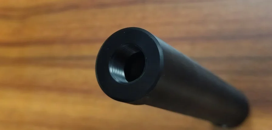
These are DXSCNC-owned photos of the actual component. The original backgrounds and visible manufacturing marks are retained. Web versions were resized and compressed to WebP without stretching or presenting altered images as additional production evidence.
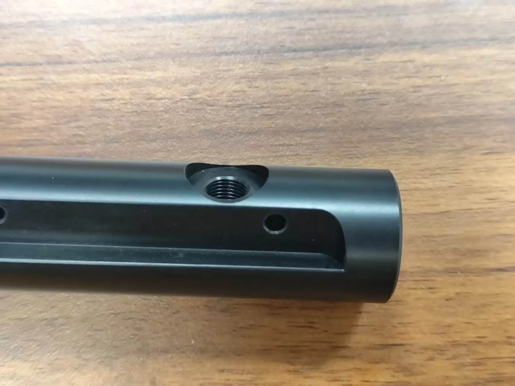
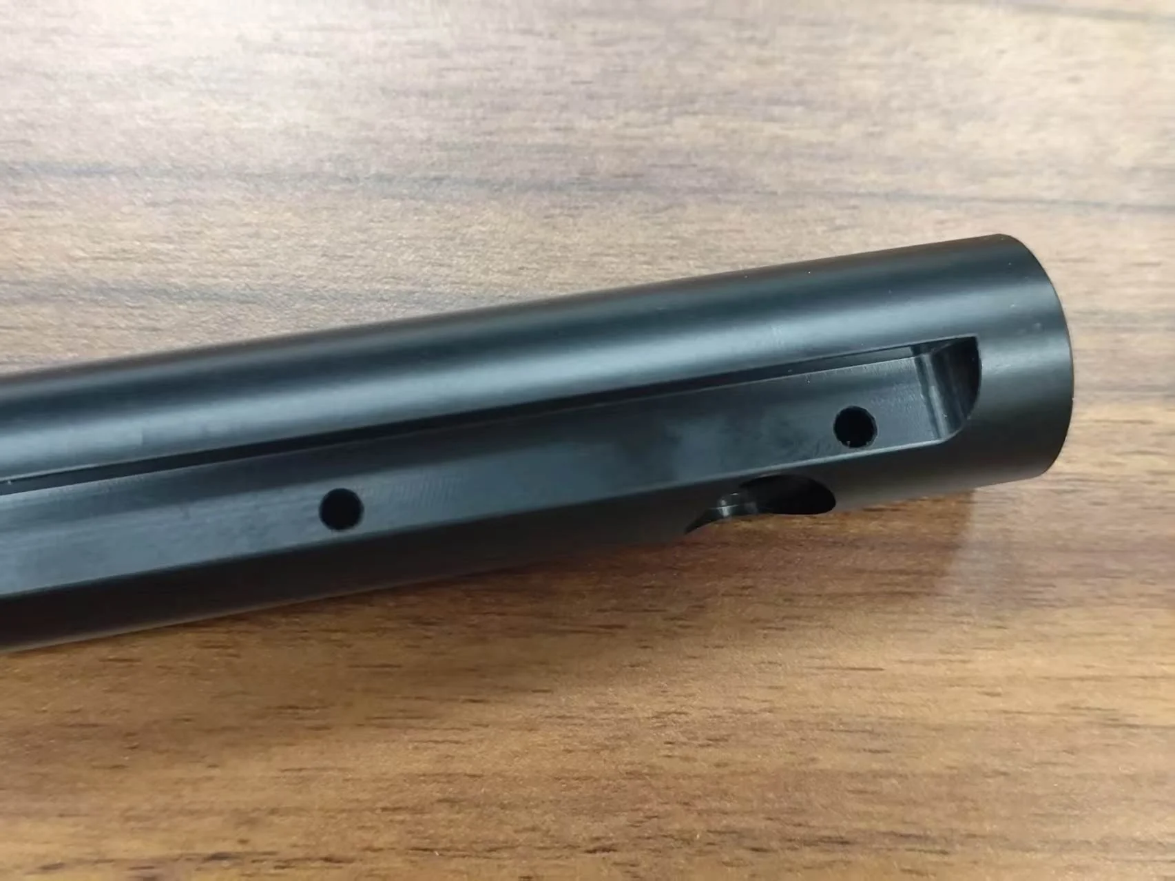
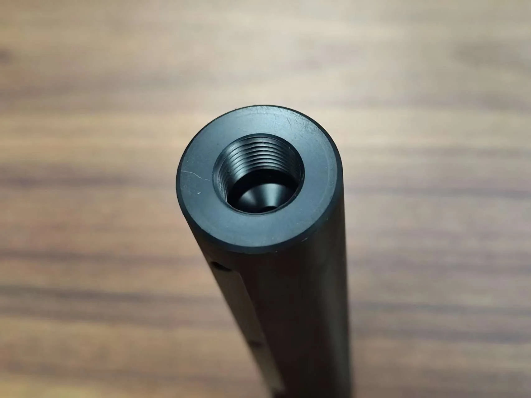
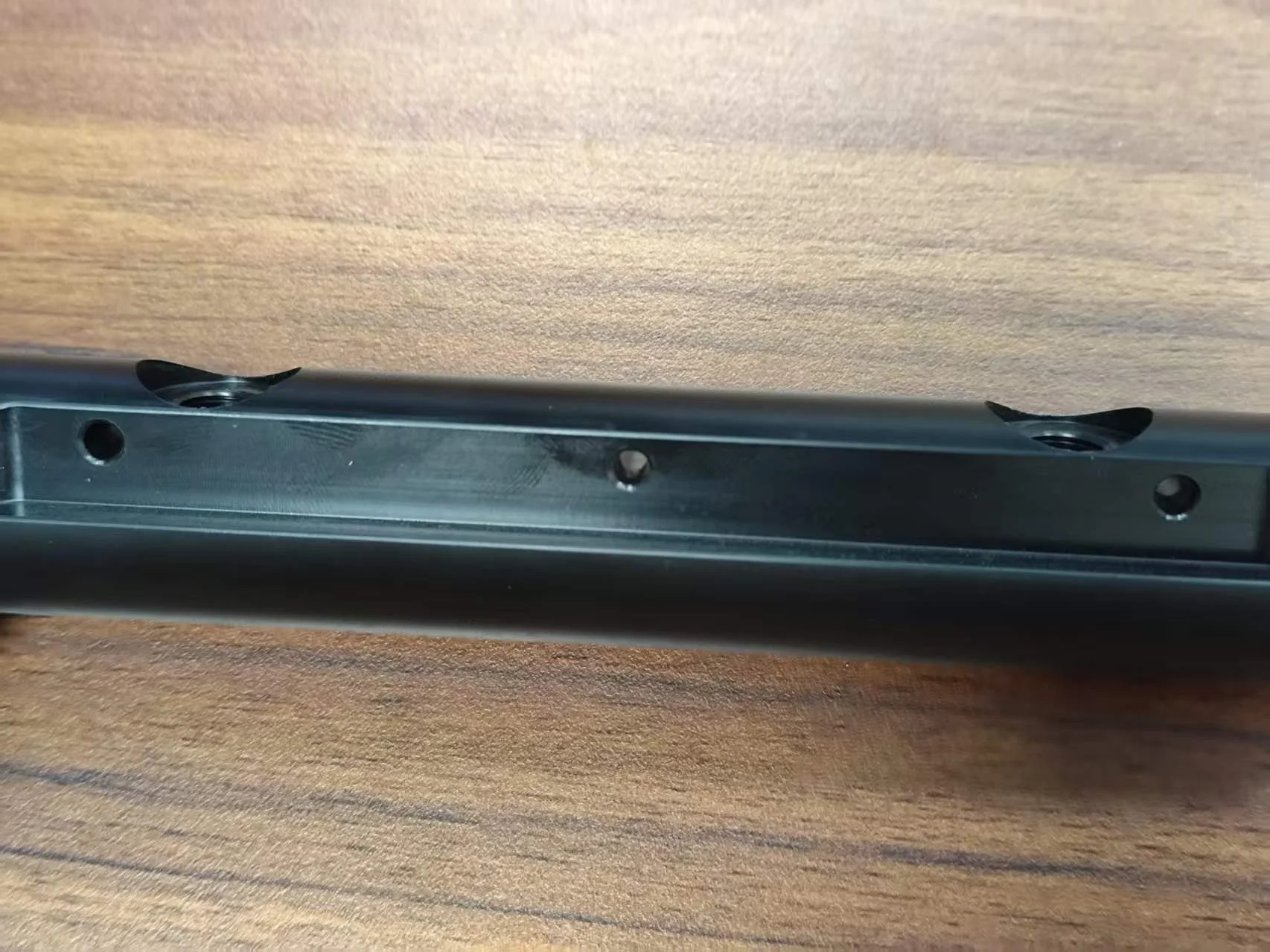
Black POM is an engineering plastic with good machinability, but a long cylindrical part can still be affected by clamping pressure, cutting heat, stress release and burr formation. The machining route must protect the outside diameter while creating internal threads and multiple side features.
The confirmed process is CNC turning and milling. The public record does not identify a machine model, one-setup claim, fixture design, cutting parameters or thread pitch.
Longitudinal milled features and side holes must be positioned relative to the turned cylindrical centerline and end references defined by the drawing.
Hole position, counterbore depth and side-thread location can accumulate error if angular and axial references are not controlled through the operation sequence.
Excessive clamping force can temporarily distort a long plastic body and affect the measured outside diameter after release.
Cutting heat and repeated machining can affect local dimensions, surface condition and measurement timing on engineering plastics.
Internal thread entries, cross holes, counterbores and intersecting side features require planned burr review because loose or raised material can affect assembly.
Black POM can show handling marks, scratches and clamp marks, so functional and visible surfaces need protection during machining and inspection.
Identify the cylindrical centerline, end references, OD tolerance, M15 thread callouts, side-feature positions, roughness and burr requirements.
Establish the outside diameter and end references used to relate later milled and drilled features.
Control the angular relationship of longitudinal milled features, cross holes, counterbores and threaded side holes.
Sequence turning, milling, drilling and threading to reduce accumulated alignment error and unnecessary reclamping risk.
Manage clamping pressure, cutting heat, chip evacuation and handling to reduce deformation, burrs and surface damage.
Check drawing-defined dimensions, feature relationships, thread condition, burrs and visible surface condition before packing.
Inspection is planned from the drawing and functional relationships. For this component type, the primary focus includes the outside diameter, end threads, hole and counterbore dimensions, side-feature position, burr condition and surface roughness requirement.
Suitable methods may include micrometers, thread gauges, height gauges, optical measurement or CMM inspection where required by geometry and tolerance. The public page does not claim a specific inspection report or result for every feature.
No separate surface treatment has been approved for public release. The black appearance shown in the photos is the confirmed black POM material, not a claimed coating.
The project-specific packing method is not public. For comparable long plastic components, packing review should protect threads, milled edges and the cylindrical surface while limiting bending, impact and part-to-part contact during shipment.
A long POM component with end threads and multiple side features should not be quoted from outside diameter and length alone. Buyers should define the functional datums, angular relationships, hole and counterbore requirements, thread specification, burr limits, surface roughness and inspection method.
This real project record demonstrates DXSCNC's ability to review medium-volume engineering-plastic parts that combine cylindrical geometry, internal threads and multiple position-sensitive milled features. It does not imply unsupported results beyond the published facts and photos.
DXSCNC will review machining range, POM workholding, heat and deformation risk, feature relationships, burr control and inspection feasibility before quoting.
Send Your DrawingRead the engineering guide to cylindrical datums, angular positioning, cross-hole and counterbore relationships, POM workholding and inspection planning for position-sensitive turn-milled components.
The guide uses this black POM production example to separate confirmed project facts from general machining guidance.
Read feature-position guideThe confirmed material is black POM engineering plastic. No separate coating or surface treatment is claimed on this page.
The public project facts identify 500 pieces at approximately 35 mm diameter x 160 mm length.
Both ends have internal M15 threads. The pitch and fit class are not published, so buyers should provide the complete thread callout in a new RFQ.
Longitudinal milled features, cross holes, counterbores and threaded side holes must maintain controlled angular and axial relationships to the turned cylindrical references.
Provide the 2D drawing, 3D STEP model, POM grade, quantity, complete thread specification, datum scheme, critical tolerances, roughness, burr requirements, inspection notes and packing requirements.
Send drawings, POM grade, quantity, thread specification, tolerance requirements, surface notes and inspection requirements for engineering review.
DXSCNC will review the part geometry and public project comparison without requesting disclosure of unnecessary customer information.